PART 5: CHANNELS AND COLOURS
Immunofluorescence experiments are almost always captured on highly sensitive monochrome cameras. This means that each fluorophore is captured as a different image with no associated colour. Often you will want to add colour to each channel (usually in the colour of the fluorophores emission) and to create composite images of 2 or more of the channels combined. This section will show you how to arrange and alter multi-channel images and change the colour of your images.
We will use the images NeuralTube.jpg plus NeuralTube Blue Saturated.tif and TrichromeIHC.tif throughout this section, along with the image set ‘RGB- blue.tif, RGB-green.tif and RGB-red.tif'.
Bit Depth
The bit depth of an image essentially determines the number of colours that can be displayed within that image. The number of colours (also referred to as dynamic range) can be calculated by the simple equation: 2^bit-depth.
Note: in black and white images "colours" in the dynamic reange refer to shades of grey between white and black.
| Bit Depth | Dynamic Range |
|---|---|
| 8-bit | 0 - 255 (or 256 colours) |
| 12-bit | 0 - 4,095 (or 4,096 colours) |
| 14-bit | 0 - 16,383 (or 16,384 colours) |
| 16-bit | 0 - 65,535 (or 65,536 colours) |
| 24-bit (also called 24-bit RGB = 3 x 8-bit channels) | 0 - 16,777,215 (or 16,777,216 colours) |
The bit depth of an image will be determined by the camera that the image was captured on. Most images are captured on 8-bit, 12-bit, 14-bit or 16-bit cameras. Three colour fluorescent images are RGB 24-bit format (made up of 3 x 8-bit colour channels).
It is helpful to know the bit depth of the camera used to capture your images so you know the dynamic range of your colours.
8-bit or RGB are the format most standard image viewers and presentation software will show. Images at other bit-depths may appear as black boxes. To allow any software to display your image correctly you can change the bit depth to 8-bit or 24-bit RGB very simply.
Select your image then navigate to Image -> Type and select 8-bit or RGB Color from the list.

Likewise, some functions of FIJI will not work on an RGB 24-bit image (ie: thresholding). You can convert a single channel RGB image to 8-bit using the same steps as above, but selecting 8-bit from the choices. In a merged RGB image you can also create 3 x 8-bit images by splitting channels as shown below.
Note: DO NOT alter bit and colour depth if you plan to do any analysis on the image, always work on a duplicate image and/or save the results of the conversion as a separate file to preserve your original image.
Split Channels
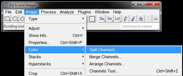
To separate the channels in a merged image go to Image -> Color -> Split Channels.
This will automatically detect and separate red, green and blue into individual monochrome images.

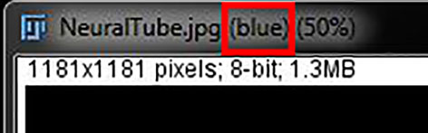
The channel will be identified for each image next to the image name.
Assigning or Changing Image Colours Using LUTs
Monochrome images have a grey look up table applied, meaning that each intensity is represented by a different shade of grey. In single channel images this can easily be changed to be different shades of red, green, blue etc. by simply changing the applied look up table (LUT).
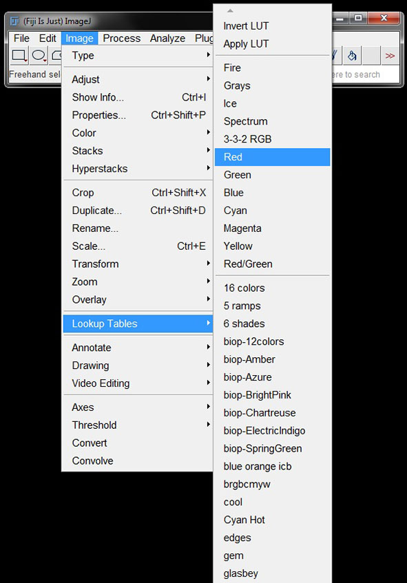
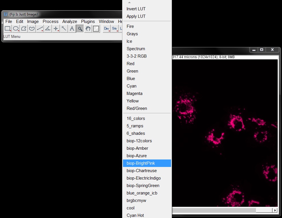
Click on the image you want to change and then go to Image -> LUTS and select the colour/LUT you want to apply to the image.
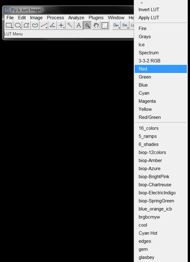
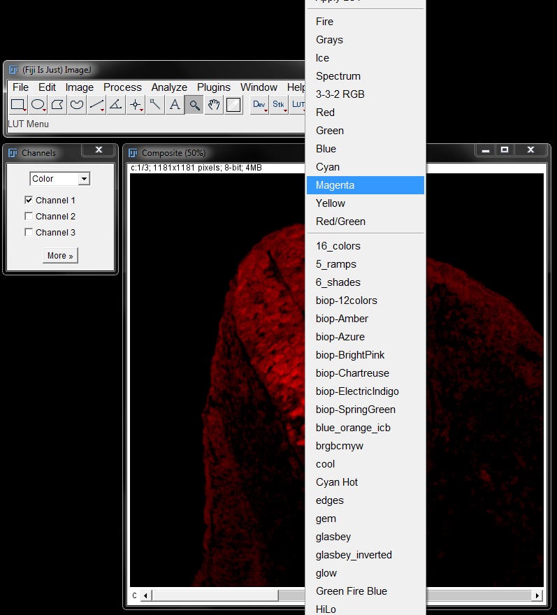
You can also find LUTs from the LUT icon in the tool bar.

Click the icon to open the list of LUTs and select the one you want to apply to your image.
To apply a LUT to your image, ensure it is active by clicking in the image, then choose the colour you want to assigne from either the menu or tool bar. Here we have applied a red LUT to the red channel from our previously seperated image.

Merge Channels
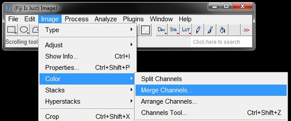
If you have individual images of channels that you want to merge, select Image -> Color -> Merge Channels.
A window will open with different channel/colour options. It will attempt to automatically input the correct images into the different channel options. It should be accurate for images which have channels assigned (such as these).

If they are loaded incorrectly you can assign the individual images to the correct channel using the drop down menus beside each colour option. All open images will be displayed as an option. For empty channels/colours need required leave the image set as *None*.
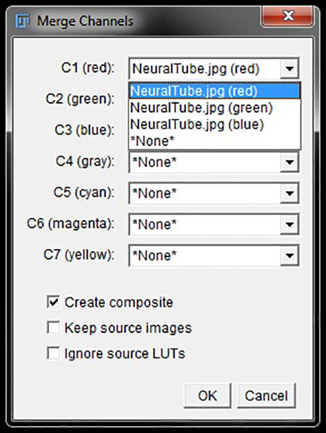
If you want to keep the original single channel images open, check the box next to Keep source images.
For a simple merge, where you do not want to continue altering individual channels you can uncheck Create composite.

However, if you want to make further alterations to channels within the merged image, keep this box selected to create a composite image. In the composite you can use the channels tool to make further changes to individual channels.
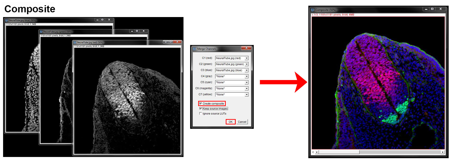
Once you have assigned your images to colours and set your options, click OK to create the merged image.
Channels Tool
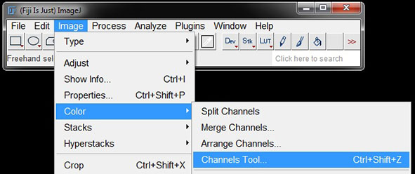
A composite image will present as a stack with each channel represented by one slice of that stack. To make alterations to channels within a composite image you can use the Channels Tools. To open this tool, go to Image -> Color -> Channels Tool (or use shortcut Ctrl+Shift+Z).
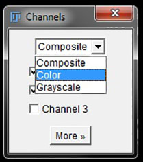
In the Channels tool window you can select from the dropdown menu whether you want to work in composite mode, colour or greyscale.
In Composite mode – all images in the stack will appear to be a merged RGB image, however the active channel will be shown by the colour box surrounding the image.

In composite mode, checking and unchecking the boxes beside an channel will turn it on or off in all images. To make changes to a channel you must move the slider across to make that channel the active channel.

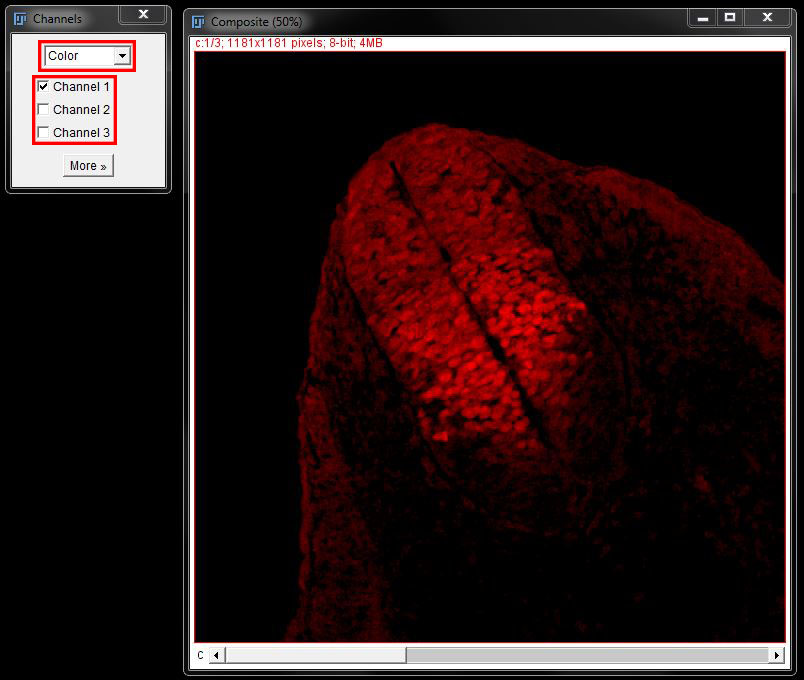
In Color – each channel will be displayed in the stack in the assigned colour. Only that channel will be visible when selected.
In Grayscale – each channel will be displayed as an individual image in the stack in grey. Only that channel will be visible when selected.
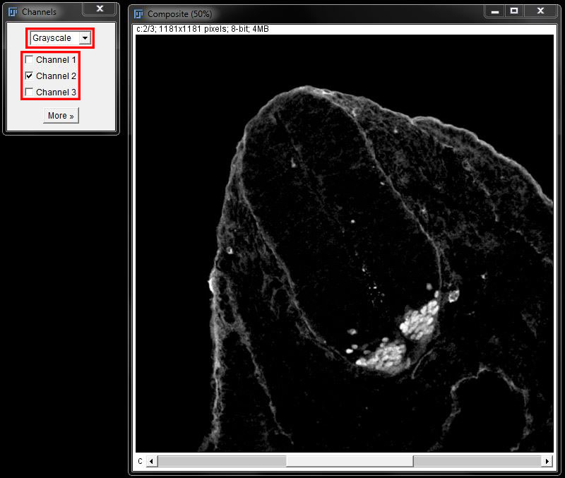
In colour and greyscale you can switch between channels by selecting the check boxes next to the channel or by moving the slider at the bottom of the image. To make changes to a channel you must select it using the check box or move the slider across to make that channel the active channel.
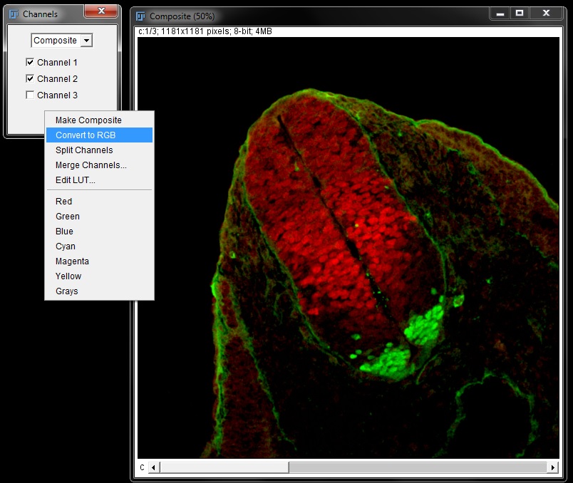
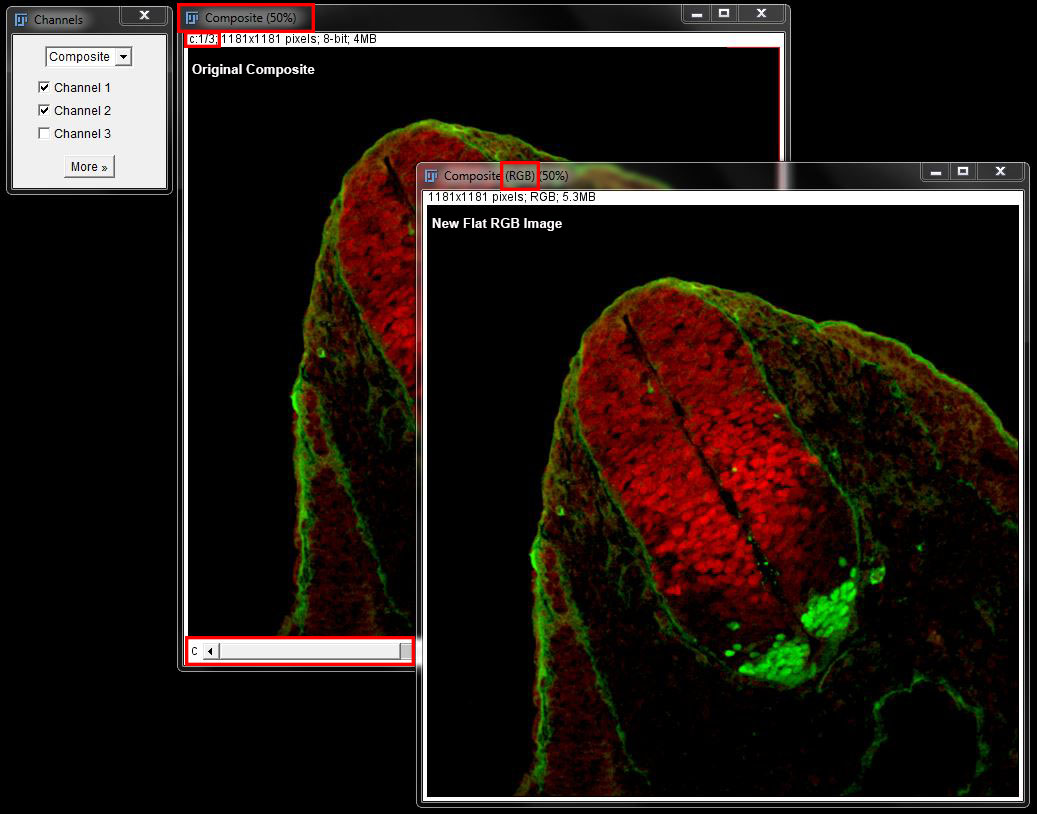
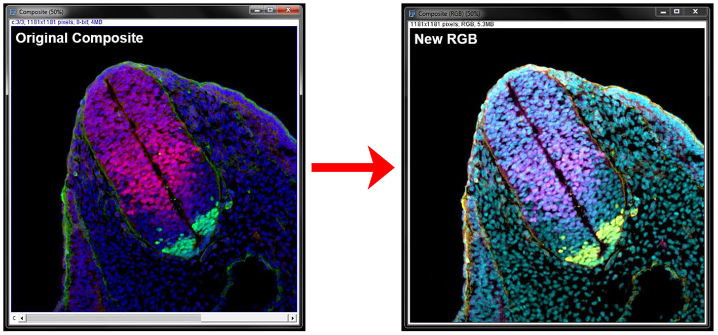
You can convert the composite to RGB at any time by selecting More -> Convert to RGB in the Channels tool window.
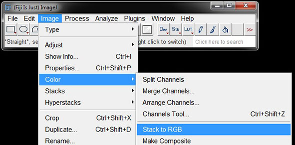
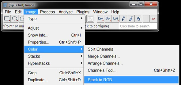
You can also convert to RGB via Image -> Color -> Stack to RGB.
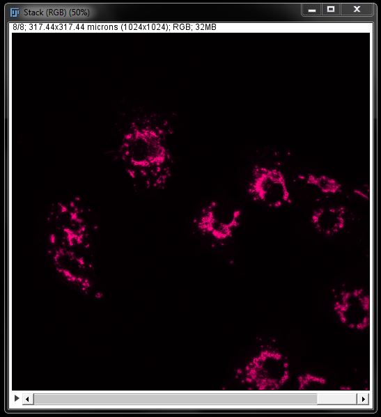
This will create a new window containing a flat RGB image of whatever is displayed in the active slice. The composite will still be availble to make further changes. In this way the channels tool is useful for saving several variations of merged images (ie: different channel combinations).
Assigning or Changing Image Colours in Composites
As well as creating different merged images, you can also use the Channels Tool to assign different colours to each channel in a composite image before converting to RGB.
To do this in composite mode, select the channel you wish to change using the slider at the bottom of the image. Then go to More and select your colour from the menu.
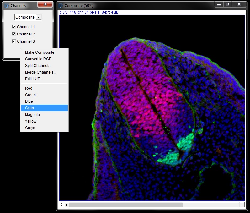
You can also do this in colour or greyscale mode by selecting the channel using the check box or slider and repeating these steps.

Colours can also be changed in composites by selecting the channel and changing the LUT using the same methods as described for monochrome images above (menu or LUT tool).
You can change all channels in the image in this way (for example chose magenta, yellow & cyan instead of red, green & blue) and then convert to a 24bit RGB image in the same way as above to create a single merged image in the new colours.
Assigning Colours and Merging Images with More Than 8 Channels
There are only 8 colour options available when using the Merge Channels tool, so in order to create a merge of 8 or more colours a different method has to be used. To demonstrate this I have opened the three channel images _RGB-blue.tif, RGB-green.tif _and RGB-red.tif several times to give me 8 "channels".
First, the images that you want to colour and merge need to be added into a stack. Open the images you want to merge then go to Images -> Stack -> Images to Stack.

In the resulting window make sure both boxes are ticked. You can give the stack a name, or just leave it as the default name - Stack.
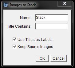
Click OK to create your image stack.
Note: The images will be added into the stack in the order they were opened in FIJI.
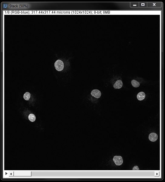
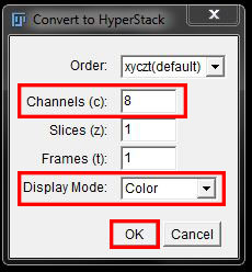
We now need to define in FIJI that this is an 8 channel image. To do this we go to Images -> Hyperstack -> Stack to Hyperstack.

In the hyperstack window, ensure the number of channels, slices and frames is set correctly (in this example 8 channels, 1 slice, 1 frame). Choose Colour as the display mode. Then click OK.
To change the colour of any channels in the stack use the Channels Tool in colour mode, or scroll to the channel and apply a LUT from the menu or tool bar as previously described.
Note: Channels tool can only display 7 channels, so to change channel 8 or higher you need to scroll to the image in the stack and apply the LUT.
Once you are happy with your colours, go to Image -> Colour -> Stack to RGB.
This will not create a flat merge as it cannot handle more than 7 colours. This step is still neccessary however to create the RGB images.
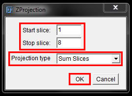
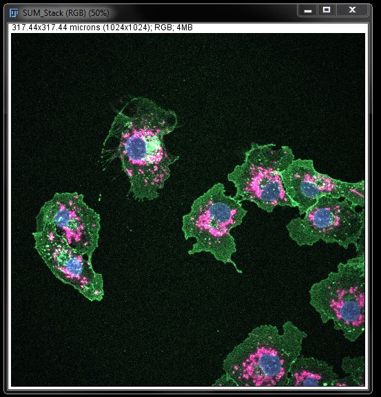
To change the RGB stack into a flat merge go to Image -> Stacks -> Z Project.
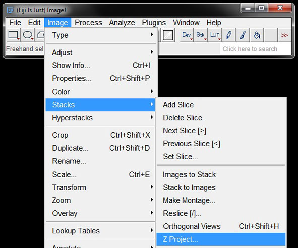
In the options, ensure all channels are included (1-8) and chose Sum Slices as the projection method. Click OK to create the flat merged image.
Inverting Images
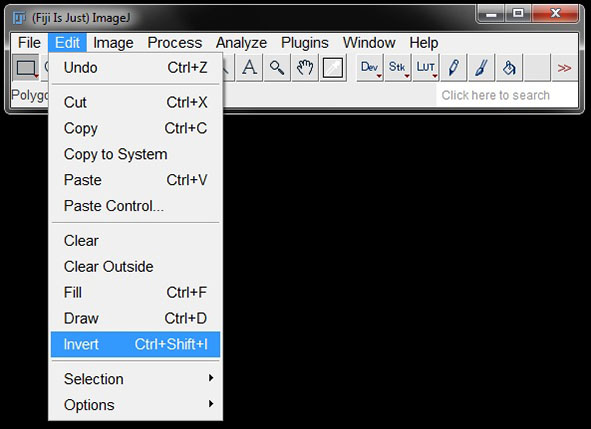
Inverting an image will switch the colour and background, or “light and dark”, in the image. To invert, select the image and go to Edit -> Invert (or shortcut Ctrl+Shift+I).

In monochrome images, such as in the example below, inverting will switch the image to a white background with black signal.

Inverting the image is reversible until saved, but it is still best to start out working on a duplicate copy of the original image and save the inverted images as a copy, with a new file name.
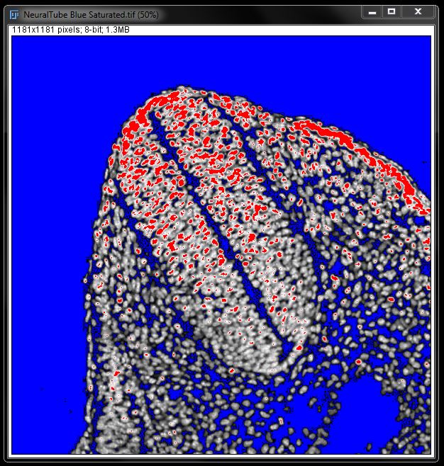
Saturation Indicator
The saturation indicator or HiLo LUT creates an image with some pixels in red and some pixels in blue. The red and blue pixels represent intensity values at the two extremes of the range. Red pixels are fully saturated (i.e. pure white) and blue pixels are fully under saturated (i.e. totally black). Both these types of pixels contain no measurable information as you cannot be sure how far above or below saturation they are.
To check the saturation levels, select your image and go to Image -> Lookup Tables -> HiLo.

In the demonstration image here (NeuralTube Blue Saturated.tif)we have adjusted the image deliberately to show a high level of over- and under-saturation, as shown by the red and blue in the resulting image.
Working with Colours in IHC Images
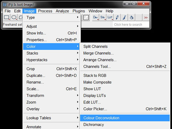
Immunohistochemistry images do not have individual RGB channels like fluorescence images. You can still separate out the individual colours for basic area or counting measurements however, using the Colour Deconvolution tool. These separated ‘channels’ cannot be used for measurements like intensity as histology stains do not work in the same way as fluorescent channels.
To find the Colour Devoncolution tool go to Image -> Color -> Colour Deconvolution.
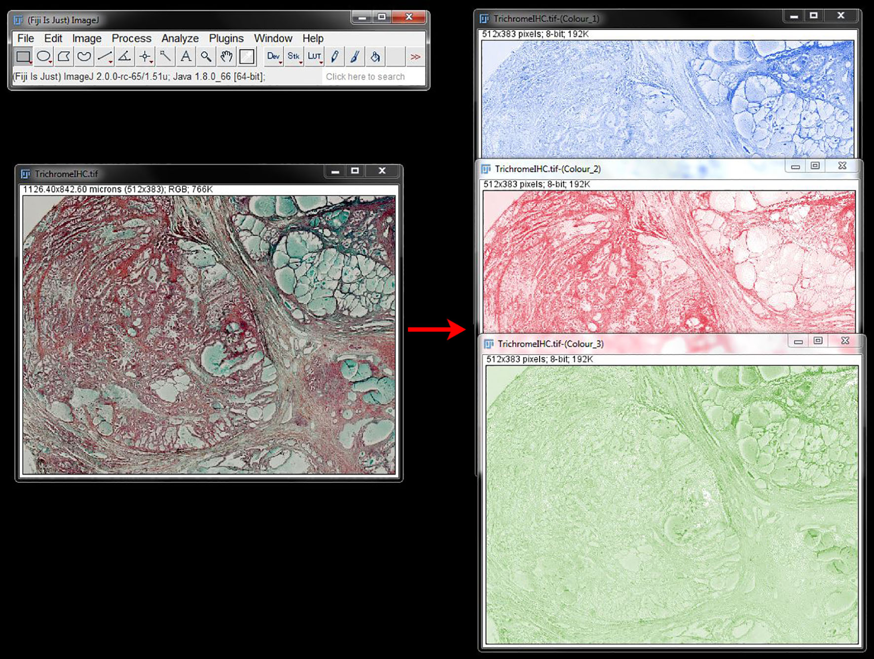
In the colour deconvolution window, there are a number of options in the drop down menu. The first option, From ROI, lets you specify the different stains in your image manually. The others are preconfigured to work with most standard histological stains. Select your stain (in this example we are using Masson Trichrome) and press OK.

This will separate the image into 3 ‘colours’ – in this case, each is representative of one dye used. For two colour stains such as H&E or Dab the two stains will be separated and a third image will display the mathematical leftovers from the equation used.
You can now use any of these ‘channel’ images for measurements like counts, or area. The methods for these are described in our FIJI Intermediate workshop.
You can also use these separated images to transform a histological stained image into a pseudo fluorescent image.
First you will need to invert each of the individual images. Do this for each image by selecting the image and going to Edit -> Invert (or using shortcut Ctrl+Shift+I).
You can then assign LUTs to each image using the methods previously described. Here we have assigned LUTs in keeping with the 'red', 'green', and 'blue' colours of the Trichrome Dyes.
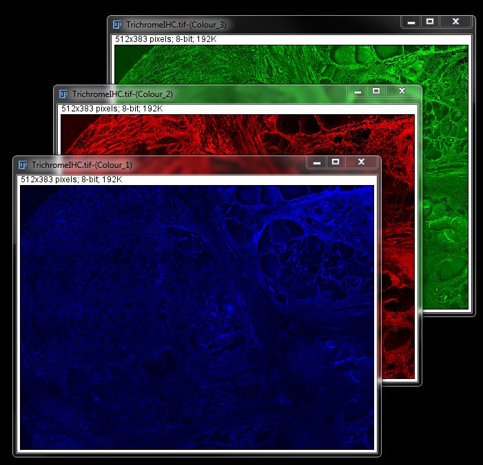
We then merge the channels as described for fluorescent images above to give you a pseudo-fluorescent version of the immunohistochemistry image.

Note: changing your IHC to pseudo-fluroescence does not make intensity measuements possible. the values are still not equivalent to a true fluorescent marker.