PART 2: BASIC NAVIGATION IN FIJI
The FIJI interface has many menus and options. In this section we will go through the basics for navigating the FIJI interface and opening and working with your images in the FIJI software.
The image Interstitium 2.tiff will be used for demonstration throughout this section.
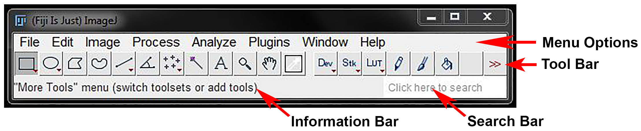
The FIJI Interface
The FIJI interface opens as a small rectangular window on your screen, containing 8 menu options and a series of buttons, which will be referred to here as the tool bar. An information bar below the tool bar will display details of the tools or image when you hover over them with the cursor.
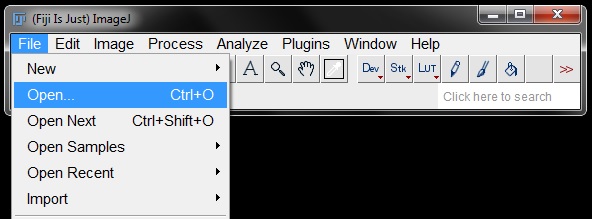
Opening Files
To open files in FIJI go to File -> Open (or use shortcut Ctrl+O). Navigate to your folder and select the file you want to open.
You can also open files by dragging and dropping the file from your folder into the FIJI interface.
If you already have a file open in FIJI you can move on the next file in the series using the “Open Next” function. Go to File -> Open Next (or use shortcut Ctrl+Shift+O) and FIJI will automatically close the current file and replace it with the next file in the folder.

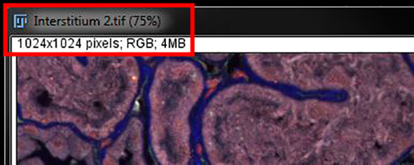
Image Information Display
Some basic image information can be found in the top left corner of your opened image. This display tells you the image name, dimensions (in pixels if scale has not been calibrated or microns if calibrated), image type and file size.
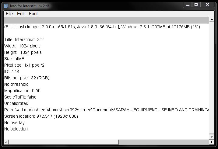
Detailed Image Information
You can find more detailed image information by going to Image -> Show Info (or use shortcut Ctrl + I).

This will display information about the image based off the attached metadata. The more detailed the metadata, the more information you will get. For example, a raw format file such as .oif will have more information than a .tiff file. In turn a .tiff file will usually have more information than a .jpg file.
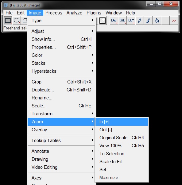
Zooming and Panning
Select the magnifying glass from the tool bar on the FIJI interface to activate the Zoom Tool.

Once the zoom tool is active you can easily zoom in and out using the mouse buttons. Left click to zoom in on the image, right click to zoom out. The position of the cursor on the image will determine the zoom centre.
Other zoom options are available under Image -> Zoom.
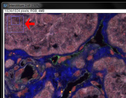
When you are zoomed in on an image you will not be able to see the entire image in the window. To move the image you can use the Scrolling Tool, also known as the Pan or Hand Tool. To switch to pan mode, select the hand tool from the tool bar on the FIJI interface.
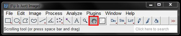
With this tool selected, click and drag with the left mouse button to move to different areas in the zoomed image. An overview window will be displayed in the top left corner of your image, showing your location within the original image.
Duplicate Image
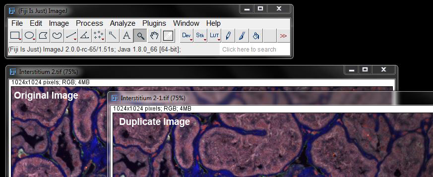
FIJI will often apply changes to the image as you work and some of these changes are irreversible. Therefore it can be useful to work with a copy of your image so that the original remains unchanged.
To create a duplicate image to Image -> Duplicate (or use shortcut Ctrl+Shift+D).
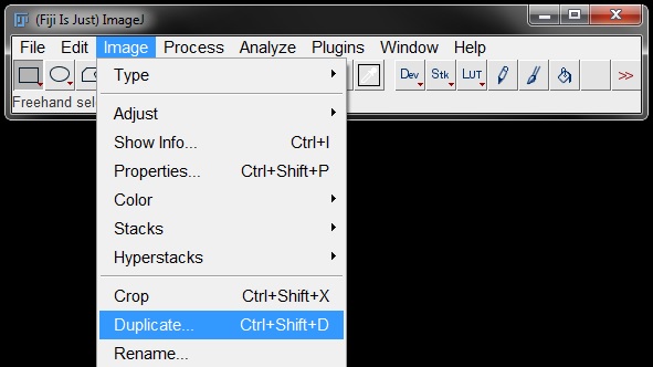
Alternatively, you can right click on the image and select Duplicate from the menu.
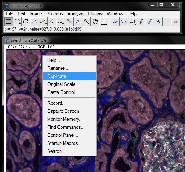
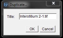
You can give the duplicated image a new name or use the default (original image name –x), then select OK.
A duplicate image will then be displayed alongside the original.
Note: When duplicating an image that has an ROI selected only the selected part of the image will be duplicated. This can be a useful tool for cropping part of an image.
Synchronise Windows
If you have multiple images or windows open that all require the same processing you can easily link the windows. This allows you to perform a single action that will be applied to all images.
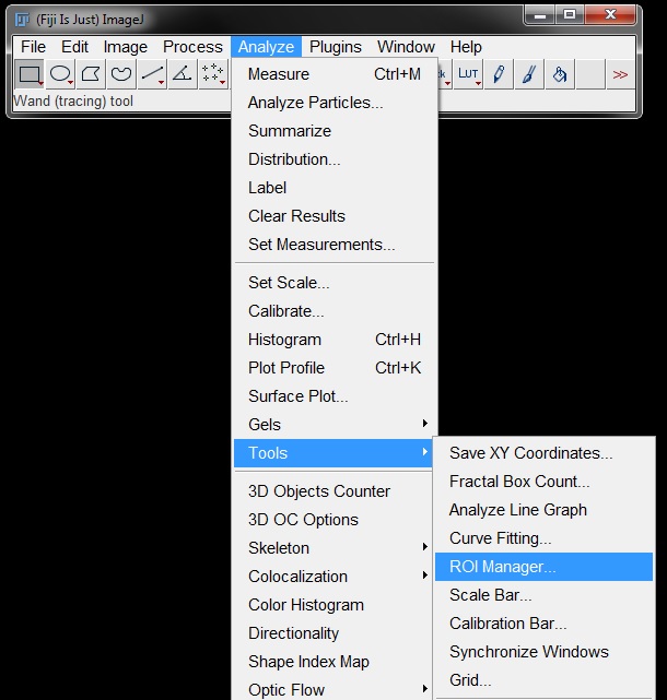
Go to Analyze -> Tools -> Synchronize Windows.

In the resulting window you can select which functions you want to synchronize and select specific images to synchronize from the list of all open images. Or you can synchronize all open windows by clicking on Synchronize All at the bottom.

When synchronized, the images will be highlighted in the list (as shown above - blue highlighted image names) and the cursor will display as a red cross visible in both the active image and the synchronized image(s).
Any movements or changes you apply to the active image will now automatically transfer to the synchronized image(s) as well. For example; scrolling through a z-series when synchronized will ensure that all images remain on the same focal plane. Or a region of interest drawn in the active image will also be displayed in the synchronized image(s).

When you have completed your tasks and no longer want to apply your changes to all images, select Unsynchronize All from the options box and images will no longer be linked.
Regions of Interest
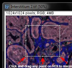
Regions of interest (or ROIs) are used to select a smaller area of an image for functions such as cropping or for analysis on that specific section. To create a region of interest choose one of the tools from the tool bar and select your area on the image.
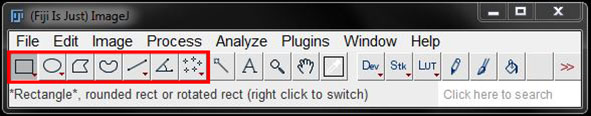
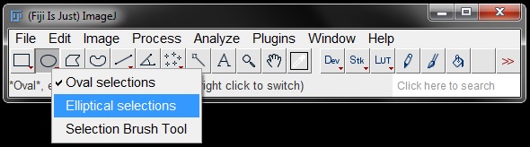
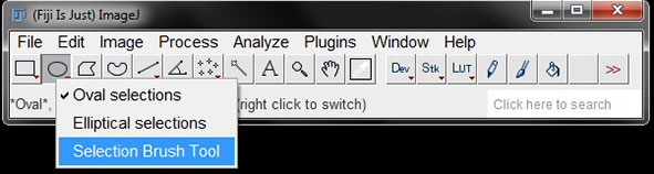
There are 7 selection tools in total; 5 simple shape/line tools and the angle and point tools. The boxes which have small red arrows indicate that several options are available in this tool category. Right click on these boxes to display the options and select from the list.
Simple Tools
 Rectangle or Rounded Rectangle tool – Creates a rectangular ROI. Hold shift when selecting the area of interest to constrain to a square.
 Oval or Elliptical tool – Creates a circular ROI. Select freely for oval or elliptical shape, hold down shift during area selection to constrain to a circle.
 Polygon Selection tool – Define your own ROI shape by clicking around your area of interest to generate line segments. Double click, or click within the small box at the first point, to complete the shape.
 Freehand Selection tool – Click and drag with the mouse to draw your ROI of choice.
 Line tools – Select which type of line you want from the drop down list and click and drag to add straight, freehand or arrowhead lines of interest on your image. Al of these are created by clicking and ragging with the mouse. Select Segmented line from the options then click along multiple points in the image to create a segmented line. The line tool also has an option when you double click on the button to set the width of the line (in pixels).

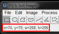
The co-ordinates and size of any ROI will be displayed in the information bar when drawing, moving or resizing the ROI.
Angle Tool
 Select the Angle Tool from the tool bar.
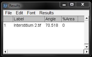
Click on three points of interest in the image to measure the angle between them.

The angle will be displayed in the information bar as you are making the selection.

Or go to Analyze -> Measure (or use shortcut Ctrl+M) to display the angle in a results window.

Point or Multi-Point Tools
Select Point  or Multi-Point
  from the tool bar (to switch: right click point tool icon on the tool bar to choose from the drop down menu).
Use this tool to select a single point or multiple points in your image for analysis. This tool is particularly useful for counting.
You can double click the point tool box to bring up options for points, such as type, size and labelling of points. For single points, options like adding to ROI manager or automatic measurement of points are also available.
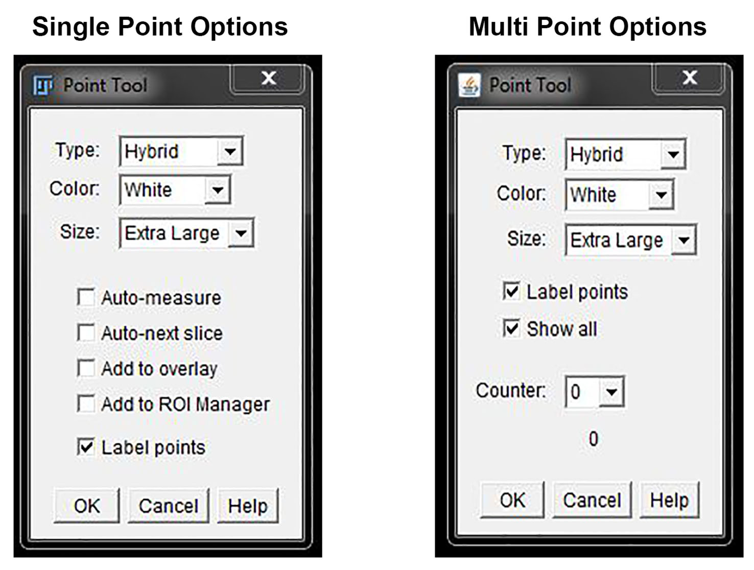
To add multiple points in your image without using ROI manager hold ‘Shift’ and select each point or use the multi-point tool. However, these will not be measured individually during analysis and essentially become a single ROI (more details on multiple selection and ROI manager are given below).
Deleting, Changing and Combining ROIs
ROIs can be modified in a number of ways after selection. This means you can undo a mistake by deleting, resizing or altering the ROI.
To delete an ROI click on the image outside of the ROI selection.
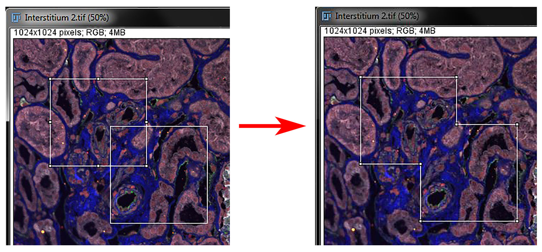
To resize an ROI click and drag on any of the small white boxes around the ROI border.
When resizing ROIs you can control the movements in several ways:
‘Shift’ + click & drag – will resize the ROI symmetrically
‘Ctrl’ + click & drag – free resize the ROI around the centre
‘Alt’ + click & drag – resize the ROI with constrained aspect ratio
‘Alt’ + arrow keys – enlarge the ROI in any direction 1 pixel at a time
Polygon ROIs will only move at the selected point to create a new shape, they will not resize in the current shape. Holding 'Shift" and clicking a point, splits it into 2 points. Holding 'Alt' and clicking a point eliminates that point from the polygon.
Freehand ROIs can not be resized, There are no points to click on within the ROI outline. Freehand ROIs must be redrawn to change the shape or size.
To move any ROI left click inside the ROI selection and drag and drop to the new location. You can move the ROI more precisely using the arrow keys on the keyboard.
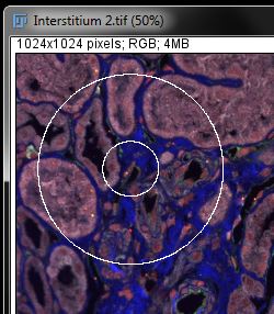
You can draw multiple ROIs by holding ‘Shift’ and drawing a second ROI of any type. However, as noted for multiple points, this is more like a merge ROIs function, as the two essentially become a single ROI and are not measured separately during analysis. This can be easily observed by drawing your second ROI overlapping an existing ROI. Once drawn the ROIs will merge into a single new shape. When using ‘Shift’ to add multiple ROIs this principle remains even for ROIs in separate parts of the image.
To select multiple ROIs for individual measurements you must use the ROI manager as described in the next section.
Holding ‘Shift’ when adding/merging the second ROI will create a symmetrical ROI. To avoid this, hold ‘Shift’ to initiate the second ROI then release it and drag the new ROI to the desired shape.
Note: If you click and drag a point within a "merged" ROI, such as that shown above, only that point will move, it will not resize the ROI in its current shape. The merged ROI essentially behaves as a polygon ROI.
You can also remove part of an ROI by holding ‘Alt’ and drawing a second ROI of any type overlapping an existing ROI. For example; hold ‘Alt’ and draw a second circular ROI inside an existing circular ROI to create a donut shaped ROI.
Note: Once this second ROI is drawn neither ROI can be resized, and as the inside of the second ROI is no longer considered a selection you must click and drag within the space between the original and second ROIs to move it. If you click 'inside' the second ROI, your selection will be lost.
Brush Tool
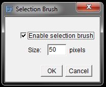
ROIs can also be added or modified using the Selection Brush Tool, which is found under the options for oval/elliptical ROIs in the tool bar. Right Click on the icon to select the brush tool from the drop down menu.
After selecting the tool you can double click on the Selection Brush Tool icon in the tool bar to change the pixel size of the 'brush'.
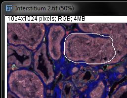
You can then use the Selection Brush Tool to paint on an ROI.
You can also add or delete regions of an existing ROI. To add a region to an existing ROI, start from the inside of the ROI and sweep outwards over the area you want to incorporate.
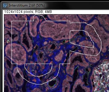
To subtract from an existing ROI, start outside the ROI and sweep the brush inwards.

ROI Manager
To measure multiple ROIs individually, rather than a single 'merged' ROI measurement, you must add them to the ROI manager. To find the ROI manager go to Analyze -> Tools -> ROI manager.
This opens the ROI Manager window.
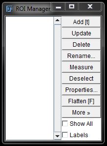
Select your ROI tool and make your selection on the image, then click Add in the ROI Manager (or use the shortcut: t). This will add the co-ordinates of the ROI to the list in ROI Manager.
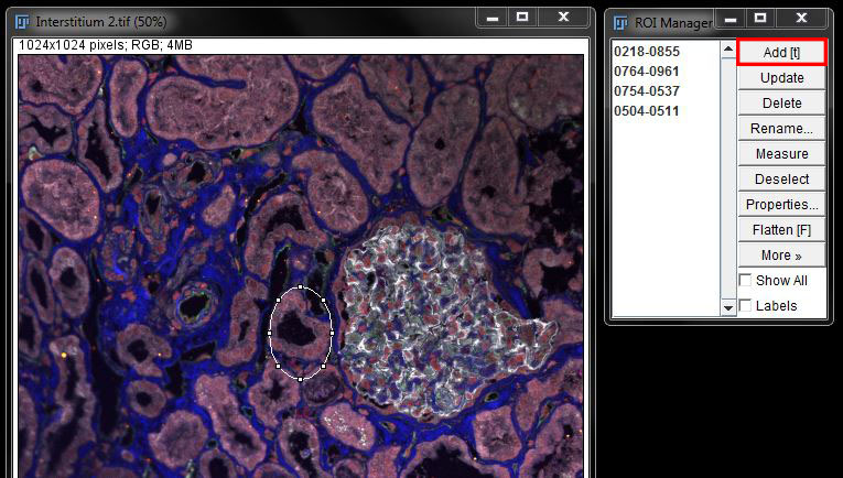
Continue drawing and adding all ROIs required. To add multiple ROIs of identicle shape and size, once the first ROI has been added to the Manager, you can then move the original ROI to a new location and click Add again. repeat this process for all ROIs needed.
Only the most recent ROI will be active, and visible, in the image, but all ROIs are saved within the image. To view all ROIs, tick the box next to Show All in the ROI manager. Also ensure the box next to Labels is selected so that the ROIs on the image will be numbered according to their position in the list.
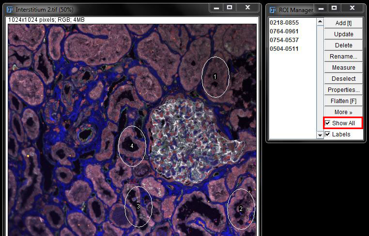
Once you have selected and added all ROIs of interest to the list, select Measure from the ROI manager options to view results. Further options, such as saving the ROI list, are displayed by clicking More in the ROI manager.
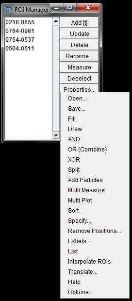
Click on a set of co-ordinates in the list to highlight an individual ROI. The co-ordinates in the list will be highlighted blue and ROI will display in the imge (or show as the active ROI if 'Show All' is selected).

You can then make individual adjustments to this ROI from the ROI manager options (delete, rename, etc) or measure it independantly by clicking measure while it is highlighted. Click Deselect to return to the full list.
Overlay ROIs to a New Image
When you have an ROI list in the manager, you can easily transfer this to a new image. Open the new image, then go to Image -> Overlay -> From ROI Manager.
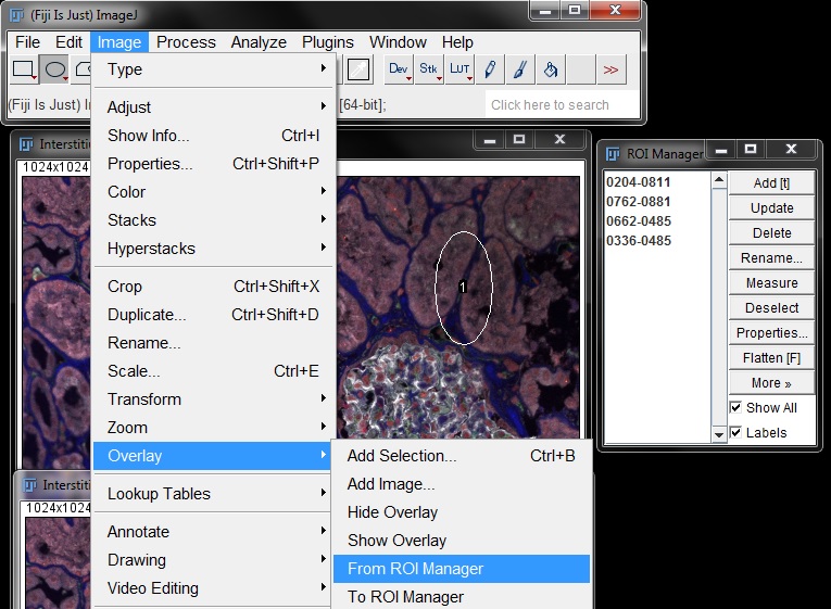
All ROIs in the ROI manager will be duplicated on the second image.
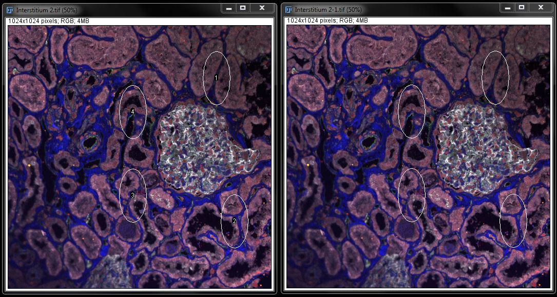
Note: These ROIs in the second image can't be resized or moved and will act as a 'merged' ROI in that only a single measurment for all ROIs combined will be given.
If you want to measure the ROIs in the new image individually that is still possible. Click on the new image to make it the active image then select one of the ROIs in the ROI Manager.
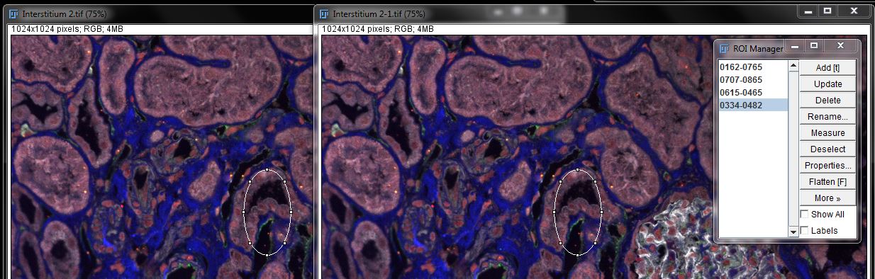
This ROI will now appear in the new image and you can click Measure in the ROI manager to get an individual measurement. Repeat for all ROIs.
Overlaying Images
You can also use the overlay tools to combine images. Here we have used an example of adding a cropped section the original image as an overlay.
Open your second image or draw an ROI and duplicate part of the original.
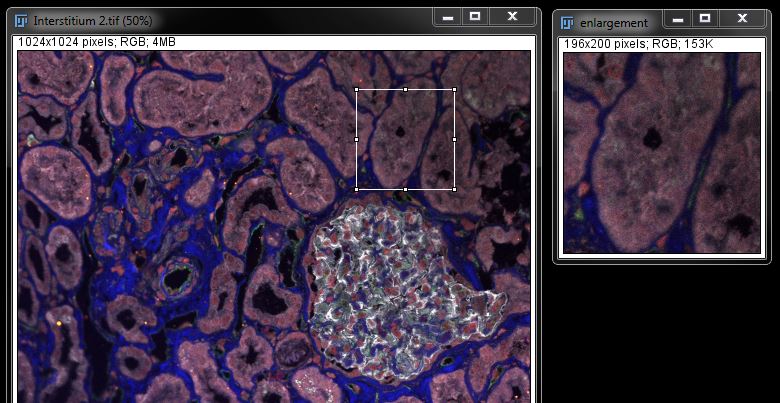
If you want to keep the ROI on your image as an outline, do not click outside the selection in the original image. Do click the title bar to make it the active image again. To keep the ROI as an outline of the area used in the overlay, go to Image -> Overlay -> Add Selection (or use shortcut Ctrl+B).

To add the second image as an overlay to the original, ensure the original image is still the active window then go to Image -> Overlay -> Add Image.

From the resulting window, select the image you want to overlay from the drop down list. You can also choose the overlay position. The co-ordinates (x and y location) for overlay position are given in pixels. Co- ordinates at 0,0 will place the image at the top left corner of the original.

Select OK to insert the picture.

At this point you can still undo the overlay by going to Image -> Overlay -> Remove Overlay. To create a permanent image with the overlays go to Image -> Overlay -> Flatten. This creates a new image with the overlays irreversibly embedded.

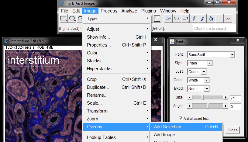
Adding Text to Images
Adding text to images can be useful for labelling and incorporating image information.
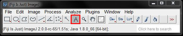
Select the Text Tool from the tool bar, then click and drag on the image to create a text box and begin typing.


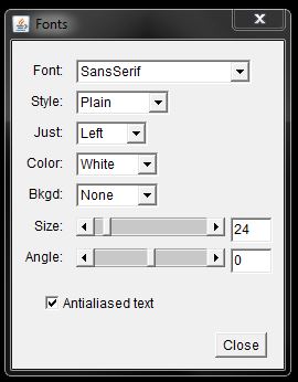
You can alter the font, size and colour by opening the text options. You can also add a background colour to the text box to allow better conrast between the text and the image. Double click on the Text Tool to open the Fonts options window. Text options can be modified either before or after typing your text and the changes will be applied.
You can move the text after adding it to the image by clicking and dragging inside the text box, similar to moving an ROI. Do not click outside the text box as this will delete the text. To keep the text on the image go to Image -> Overlay -> Add Selection (or use shortcut Ctrl+B).
You can then work with the text as you would any other overlay (show/hide/remove) and select flatten to create a new image with text completely incorporated into the image. If you are working with a stack, this option will only add the text to the first image in the series.
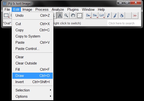
You can also go to Edit -> Draw (or shortcut Ctrl+D) to incorporate text into the image, but this will keep text only. If you have a background colour this will be lost with this option, so ensure your text colour is clearly visible. When working with stacks this option will allow you to apply the text to all images in the stack.
Saving; Formats, Options and Image Quality
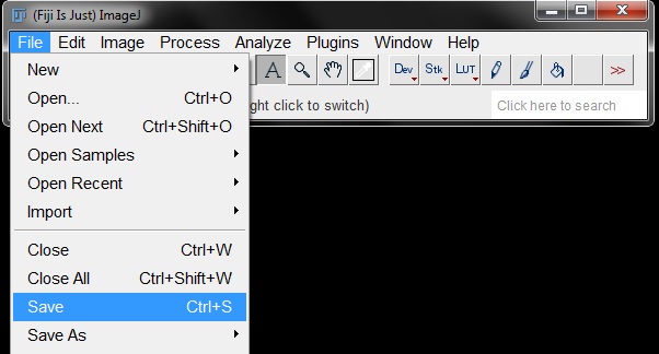
To save changes go to File -> Save (or use shortcut Ctrl+S). This will overwrite the previous file and save any changes. If it is a new image the default save format is TIFF (as imagename.tif).
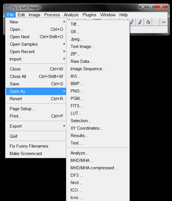
To choose a specific format for saving, got to File -> Save As, and select the format you want to use for the image from the list. Select your folder and name your file as you normally would. Commonly used file formats include: TIFF, JPEG, AVI, PNG, EPS, PDF.
Unique, but Useful, File Formats
Image Sequence: saves each image from a stack as an individual TIFF file. You can select numbered images or use slice labels for naming.
Selection: saves ROI(s) for re-use at a later time
XY Co-ordinates: saves ROI(s) as a text list of x and y co-ordinates
Saving Measurements
Use Save Results from the file options to export all data in an active results window as a text file.
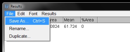
Or; to export results as an Excel file, click on the results window and within the window select File -> Save As.
Select your folder and name the file as you normally would and select the file tye (.csv, .xls, etc) from the drop down menu. Click Save to export the results file.

An Important Note on Image Quality and Compression
Far too often people save their data directly from the microscope as a JPEG file. The JPEG file format seems good in theory, as the file sizes are smaller and it save space on your hard drives. But JPEG is what we call a ‘Lossy’ format. When you save as a JPEG your images are compressed – this is achieved by REMOVING PIXELS FROM THE IMAGE DATA.
This image information that is lost with JPEG compression can NEVER be restored. Even if you resave with a different level of compression or in a different file format the loss is irreversible. The more you open, edit and re-save a JPEG, the more information is lost.
To maintain the quality of your images and the integrity of your resulting data, ALWAYS save your original data in the raw format (ie: .oif for Olympus, .nd2 for Nikon, .lif for Leica, etc) and keep the original raw file untouched. Save your working copies as TIFF files to avoid compression and loss of image quality and data. Only save as JPEG for the final version to be submitted to journals or used in presentations AND KEEP THE ORIGINAL AND THE TIFF as well for any further editing that may be required.
If your original data is requested by a journal, which is happening more frequently these days – sending them JPEGS will not be acceptable.
To maintain quality and integrity of your data, remember these points when working with and saving your files:
- Always save from the microscope in the raw file format and keep that copy untouched
- Keep an unedited backup – duplicate your image and make the changes on that as some edits are irreversible, save and keep both copies as TIFFs
- Loss of pixels = unreliable measurements
- Save working copies as TIFF files to avoid continual compression
- Only go to JPEG at the very end for a final ‘submission’ copy of the image